"Ruby" the Riley Pages: 1 2 3 4 5 6 7 8 9 10 11(new) UPDATED: 22 August 2021 |
The AC fuel pump has been dismantled and cleaned-up - just waiting for a new kit and hopefully a good second hand lever arm. Problems exist in the lever arm and... 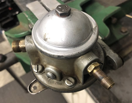 |
|||
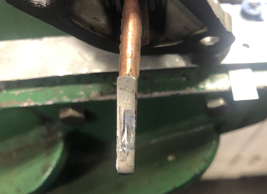
This is the rocker arm from my RME AC Type "U" mechanical fuel pump. The section which bears on the camshaft eccentric can clearly be seen as a hollow area where it should be flat. It was 0.025" depressed (worn) where the excellent "Fuel System Supplement" indicates that slight wear is permissable but not exceeding 0.010" |
This is the same rocker arm which I have had modified by Fimac Engineering 17 Ridge St, Bega NSW 2550 (02) 6492 2805 They have metal sprayed the surface to build it up and then machined it flat (Hardness approx 39 HRc). So second hand ones can be saved. This one cost $85 but savings can be made by doing batches. 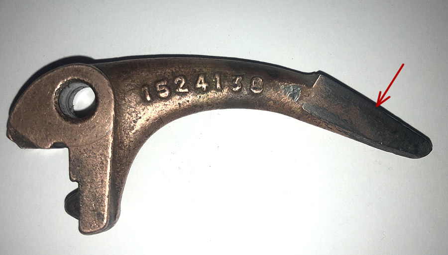 |
||
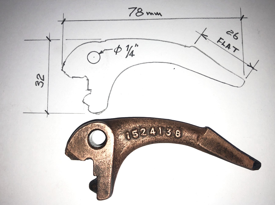
The eccentric on the cam which operates the fuel pump is quite narrow and explains why it is so easy for the arm to be bent if it was running out of true. 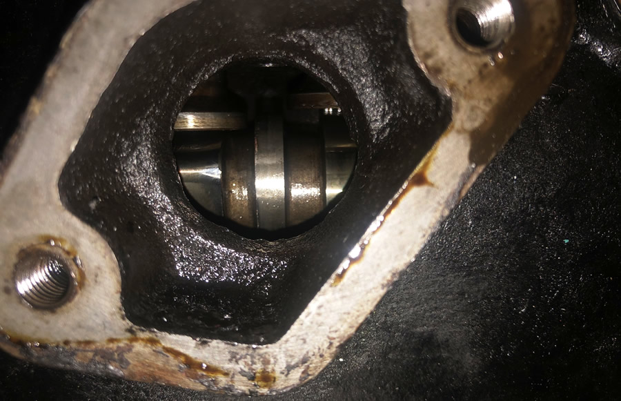 |
As indicated on the previous page, I have elected to fit a (Davies Craig) 14" thermofan. 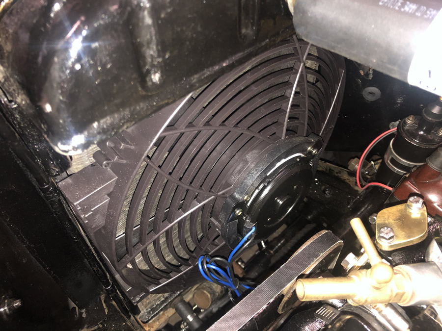 |
||
By good fortune, the mounting holes in the fan line up with the flanges on either side of the radiator so 4 self tapping screws were used. Care needs to be taken to get the screws in line with the middle of the flange. 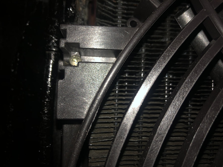 |
The blue tape is holding the clips used to hold the wiring loom in place near to the existing mounting holes. I took dozens of photos to remind me of what goes where - but I wish I had taken more! 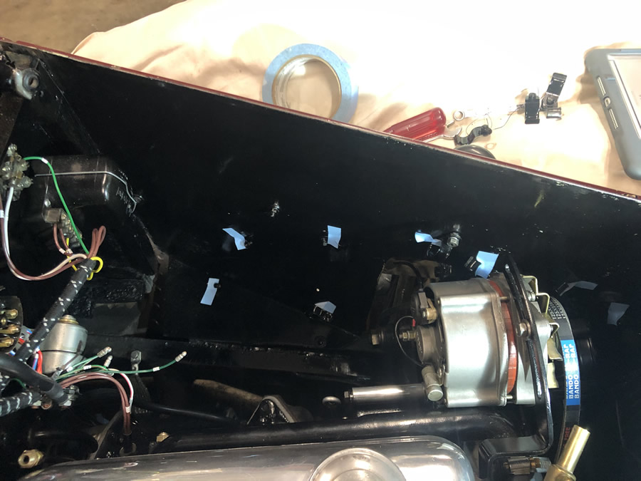 |
||
WIRING LOOM At first it seems like you will never figure out where everything goes but the loom is provided in several sections. I started at the end named "Cowl" which is the dashboard area. All of the wires are correctly colour coded and labelled at all ends with an alpha/numeric code and a page of instructions. Starting in the dashboard area was useful as the wires to the dipswitch on the drivers side made it clear where that bundle had to go. |
|||
1
I am not sure that the wiring layout I have used is as per the factory. The location of the Junction Box (JB), Fuse Box (FB), Control Box (CB) & Starter Solenoid (SS)are correct as they match the holes in the firewall (and my photos). 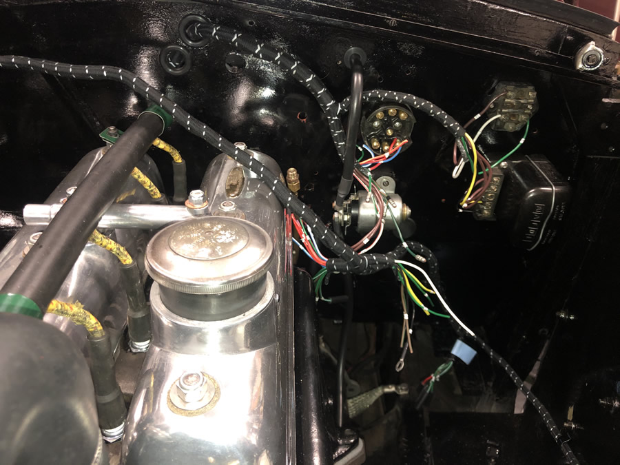 |
2 The Cowl loom has been temporarily attached to the FB, SS & CB. I then realised that another section went along the inside of the pass. side engine bay with a branch diving down to collect to the separate Tail Light section. 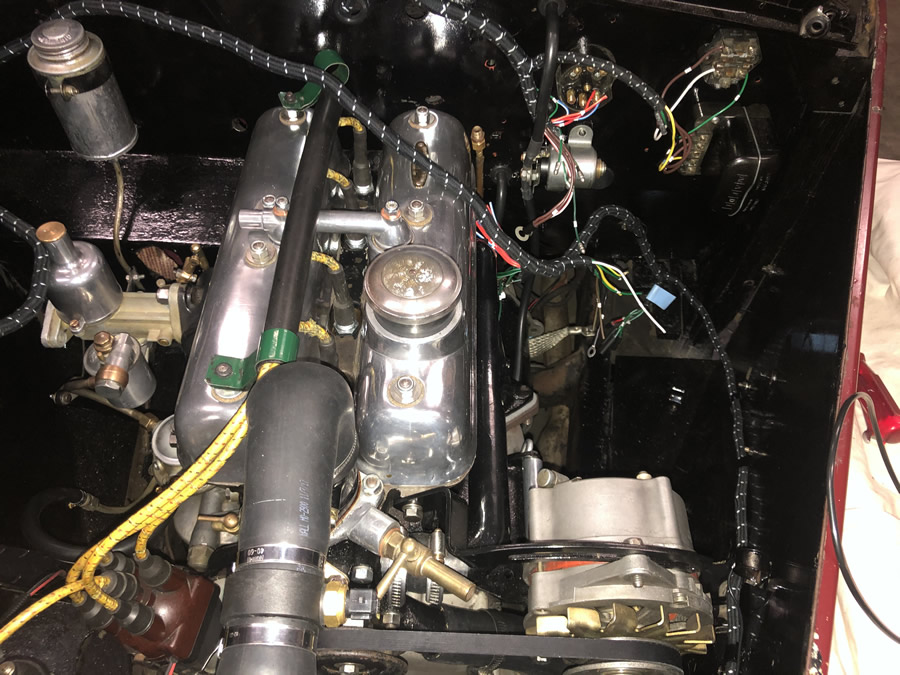 |
||
3
|
4 From the previous photo the wiring actually dives down under the front of the car to connect to the wires from the steering column and to the horns etc. on the L/H side ... ( 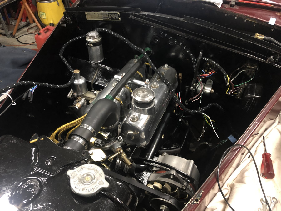 |
||
5 Once the various parts of the loom which connect to the JB, FB etc were in place, and using some old Riley engine bay photos, I was able to clip the main branches of the loom to the bulkhead. A series of 3/16" holes revealed where most of the clips went. 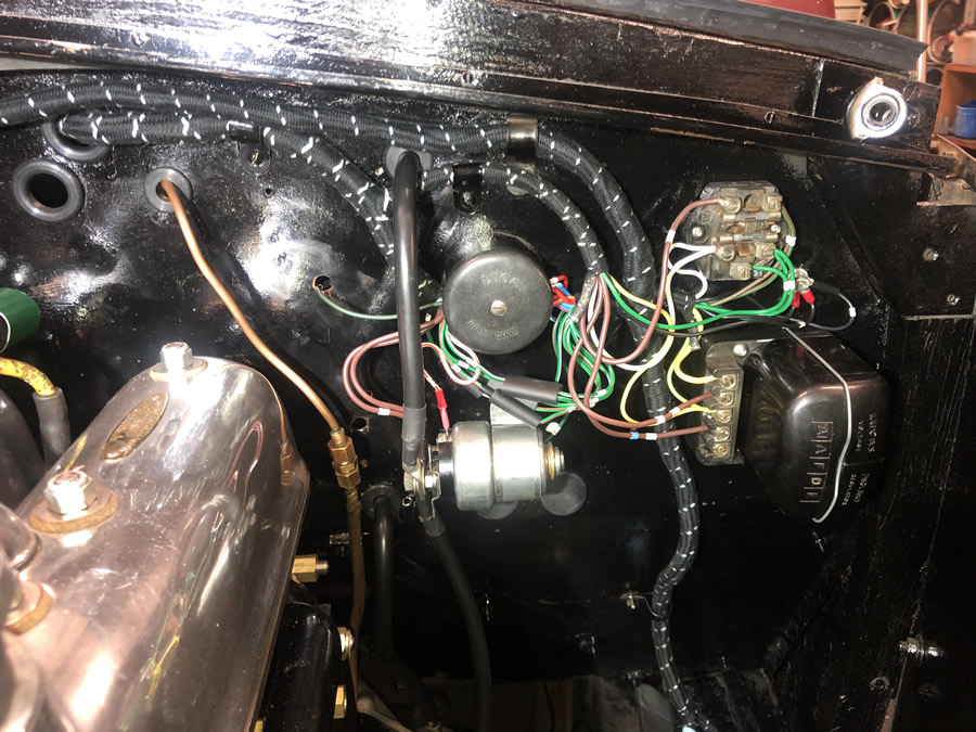 |
6
Moving in to the dashboard, the necessary parts of the loom connecting to the instrument panel were laid in place. The blue wires connect to the dip switch which is located on the RHS of the dashboard - so it was clear where that branch went. 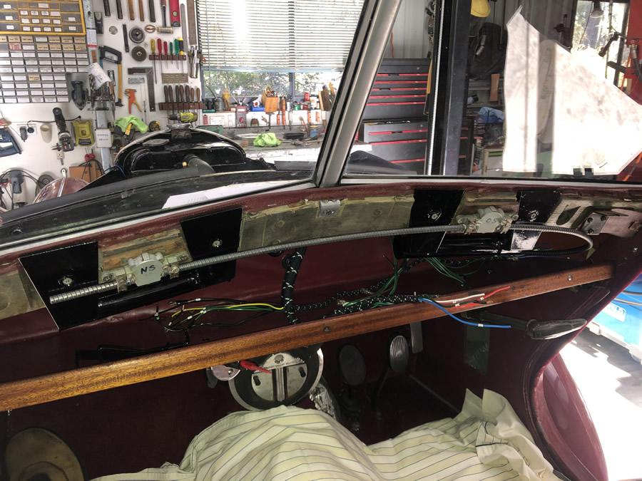 |
||
Still adjusting what goes where in the engine bay. The capillary tube for the temperature gauge is quite long. Apparently it runs along, and is clipped to the radiator brace which is not fitted yet (end is circled top left) and is looped in several coils to drop down to the connection in the block (circled right) 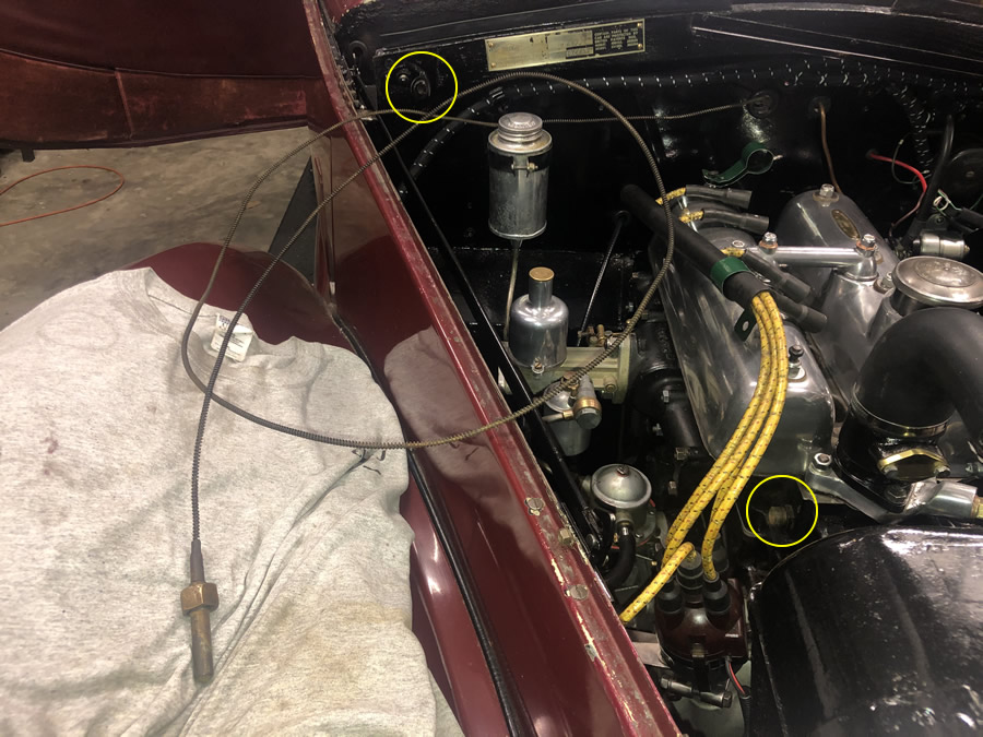 |
The dashboard is back in place but not quite complete. The clock is missing and I had a bit of a disaster with a 'self dismantling' ammeter. All the lights in the front of the car are working correctly including the wiring through the stator tube (horn, blinkers & trafficators which all work). The cable controls to the distributor and carby are yet to be refitted. 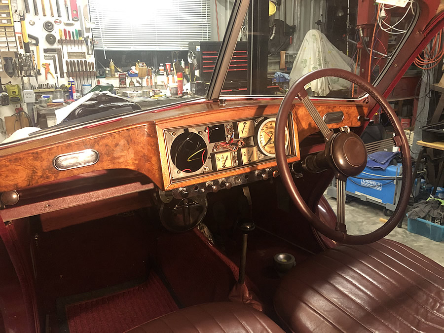 |
||
Things got a bit carried away here as I finally managed to get the valve settings and ignition timing sorted out. The result was the unexpected first test run of the engine which came as I tentatively hit the starter solenoid. Lo and behold, we had action but at about 2000 RPM as the hand throttle was not set to idle! |
|||
VIDEO 1 : - Here is the first run of the engine since 2019 - the valve clearances are generous and noisy and the idle was a bit high. Oil is splashing around and the feed line to the oil gauge was leaking badly as I had not tightened the union.
|
VIDEO 2 : - Second run with the rocker covers on and less oil flying about. The idle was now set a little better and the motor ticked over nicely considering I haven't set the ignition timing correctly yet. The air cleaner is yet to be fitted.
|
||
|
|||
First Drive - just off the hoist and into the back yard! I'm not sure who had the biggest surprise: me when Ruby fired-up or Joan when she came out of the house and saw Ruby parked there. 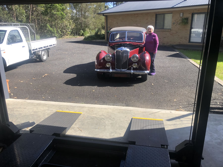 |
In this photo and the one to the left you can see the brown ash coating on the roof, left over from the terrible fires in the last year. The oil track on the ground was caused by the loose connection to the oil gauge. Fortunately it was not the one on the back of the gauge. 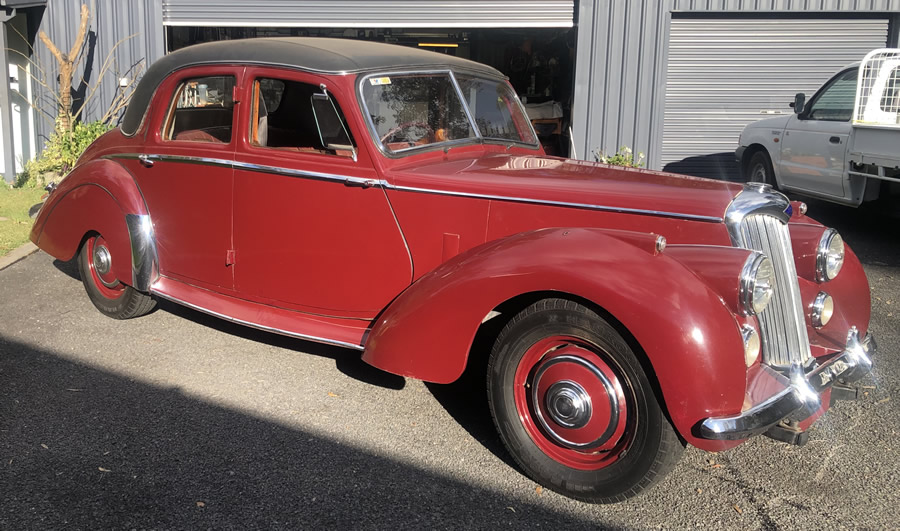 |
||
Back to bed on the hoist after a wash. The wipers are askew because I had reinstalled the wiper mechanism incorrectly. The N/S wiper wheelbox was UPSIDE DOWN! Instead of the blades meeting in the middle, they swing in parallel... wrong. 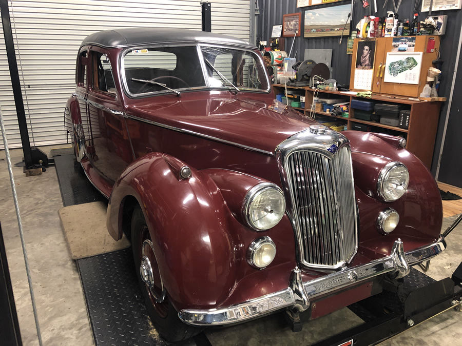 |
It is suprising how the burgundy colour changes in different light conditions. The photo to the left was taken under flouroscent lights and looks almost brown. There is still a lot to be done: As mentioned earlier, I haven't installed the section of wiring loom from the engine bay to the tail lights. I will be using that part of the old loom until I can get the rear half of the chassis and underbody cleaned up.
|
||
Ignition comparison - Pertronix Ignitor Electronic Ignition top left and standard points at right. I do prefer the latter for setting up the timing. But once set, I will use that setting for the electronic unit. 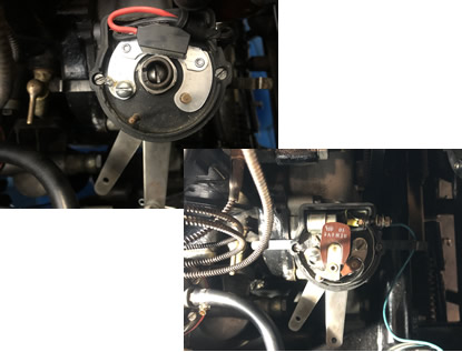 |
|||
"Ruby" - here she is, washed & clean albeit with cross-eyed wipers!
|
Here I am repairing the error made by fitting both wiper wheelboxes the same way up. Luckily the RME wooden dashboard can be removed without disturbing the instruments. The N/S box is now upside down & correct. 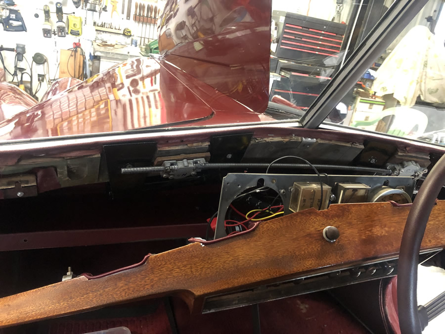 |
||
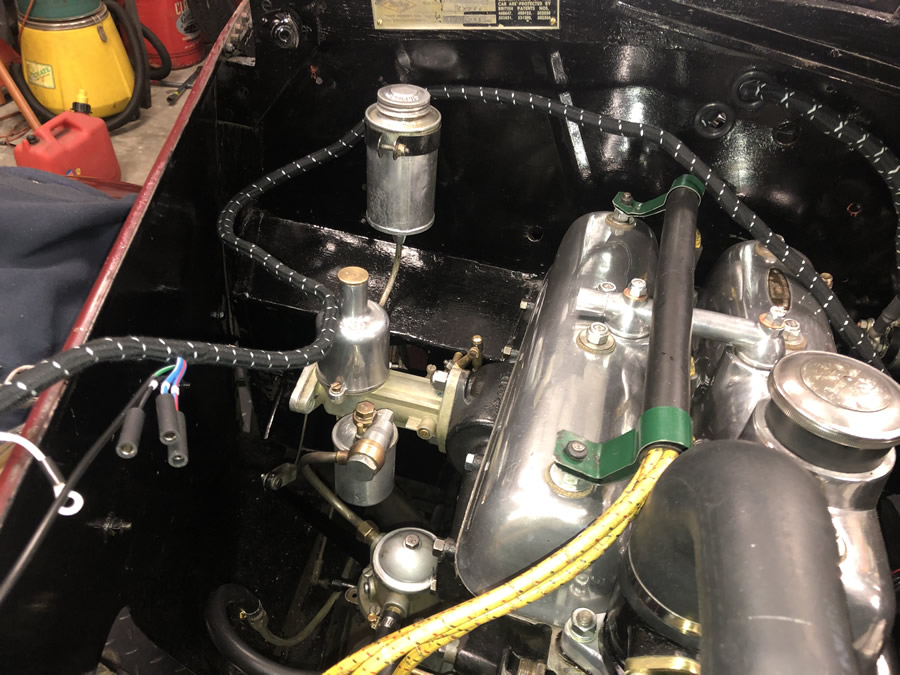
Nearside engine bay. 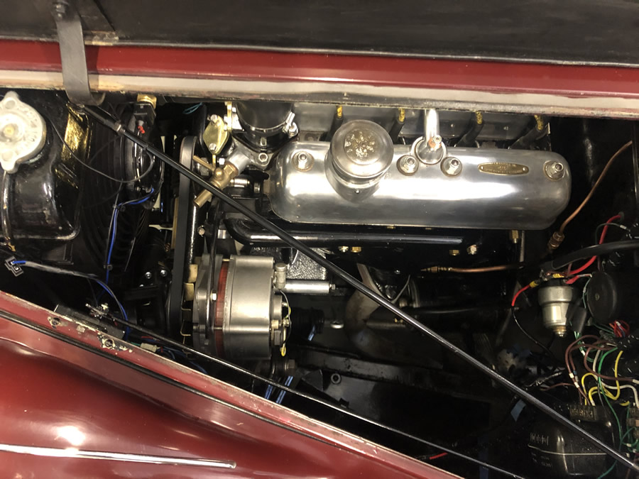 |
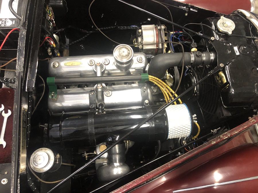
Offside engine bay. 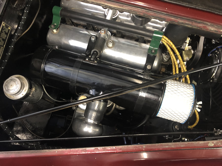 |
||
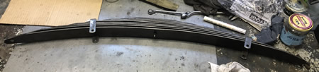
Just a reminder - this what the rear springs were like. I had to remove the N/S one first as it had sagged considerably .... 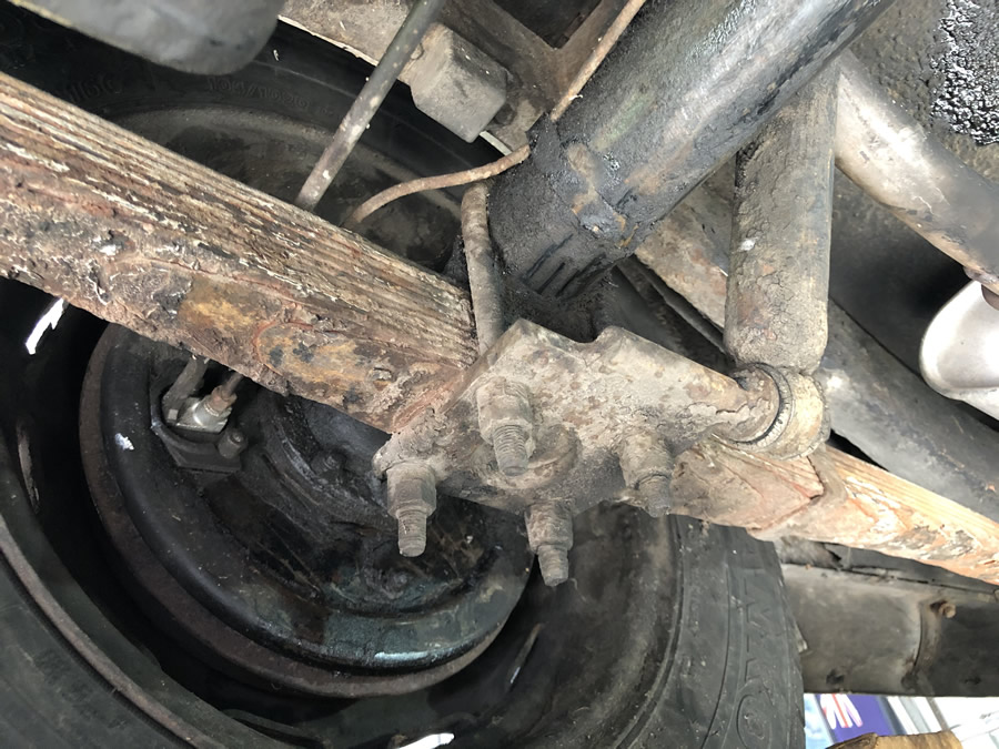 |
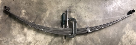
Here I have dismantled the spring and cleaned up each leaf. Note the missing wrapper around the 4th leaf down. I will have to make a new one and rivet it in place. 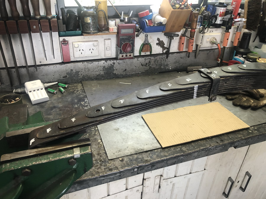 |
||
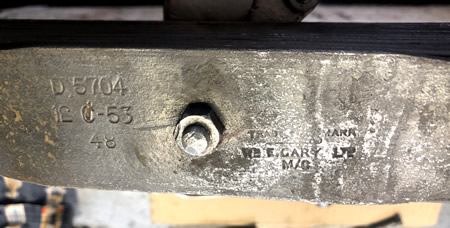
Here is the manufacturers mark on the spring confirming the build Year of the car. |
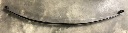
Profile of the top leaf. I used this as a guide to cold press the spring leaves.
|
||
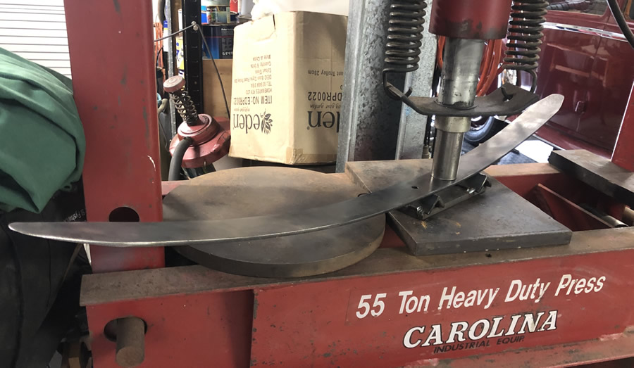
This was the setup I used to progressively bend the springs by sliding the spring along keeping the ram between the 2 formers (5" apart). A small 10T press would be fine. |
All the leaves are going back together ... ---and here you can see the deflection from the original chalk line. |
||
To produce the missing spring wrapper I had to make a new rivet. 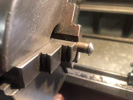 |
Here is the missing piece fabricated from mild steel. 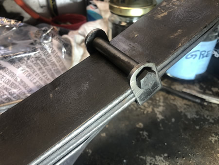 |
||
As I will need to shorten a few shackle rubber bushes I rigged up this knife clamped to the tool post so that I could neatly part them off to the same length. 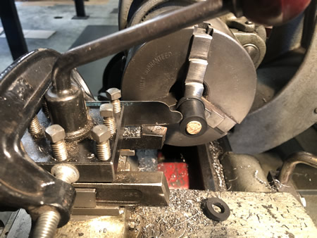 |
Here is "Ruby" paying a visit to the house garage to have a coating of shoe polish on the roof. From the accepted wisdom on the RM UK Forum I will give it a go and I expect it will be fine. 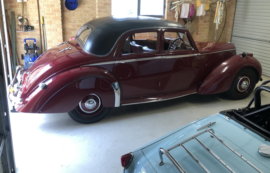 |
||
Getting close to registration now! 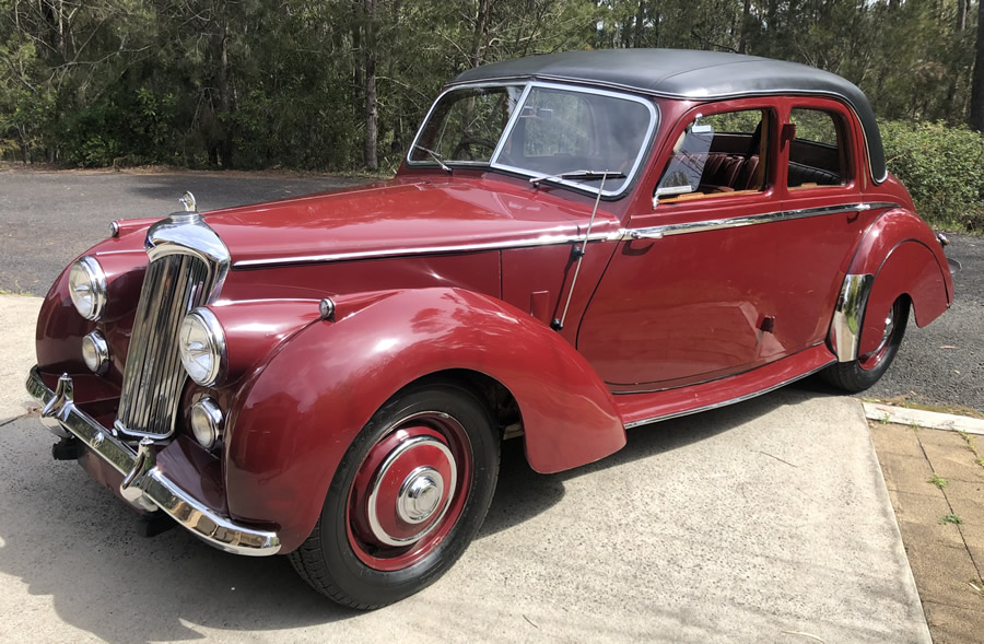 |
The interior has come up quite well - thanks Bill and Julie! 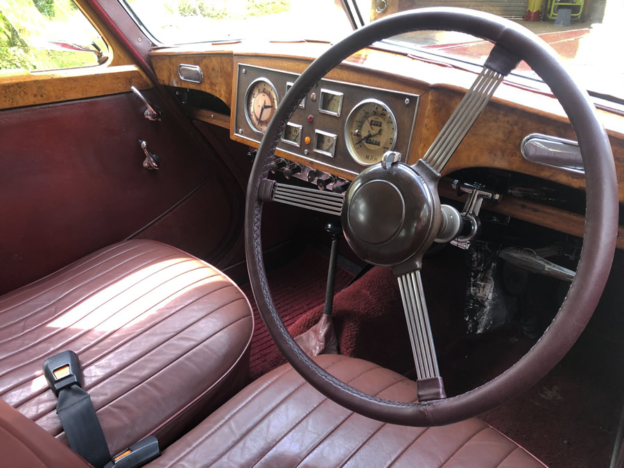 |
||
After use we feel the need to have the seat padding improved. That is under way (July 2021) |
|||