"Ruby" the Riley Pages: 1 2 3 4 5 6 7 8 9 10 11(new) UPDATED: 22 August 2021 |
VIDEO: - This little video shows a bench test of the Lucas type CRT windscreen wiper mechanism to check if all will be well when it is installed. All the old grease was cleaned out and replaced with a low viscosity Moly grease.
|
In some cases it is good to have photos to show how parts go back together. In this case the wiper "wheelbox" and the screen demister AND the support for the top end of the steering column (under the wheelbox). NOTE - it was pity I hadn't check the dismantling photos as I had fitted the N/S wheelbox UPSIDE DOWN!
 |
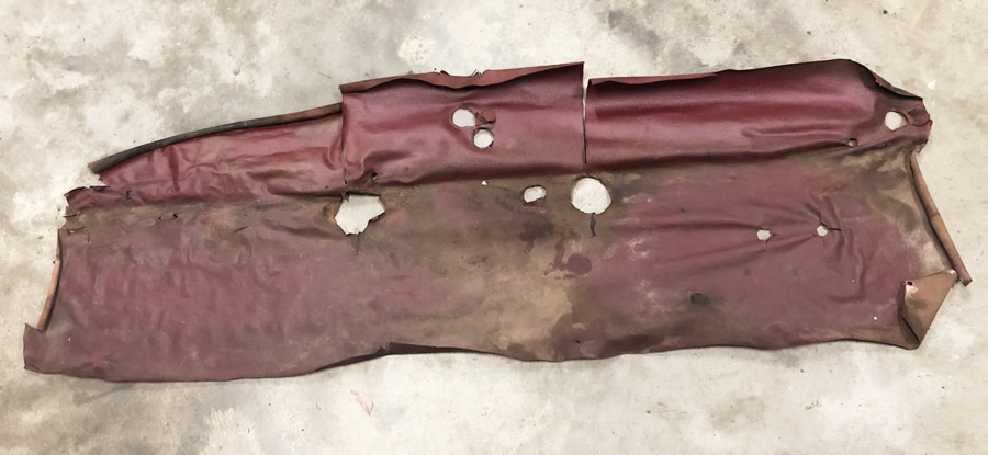
This doesn't look much but it will provide a working pattern for making a new leathercloth covering for the parcel shelf.
 |
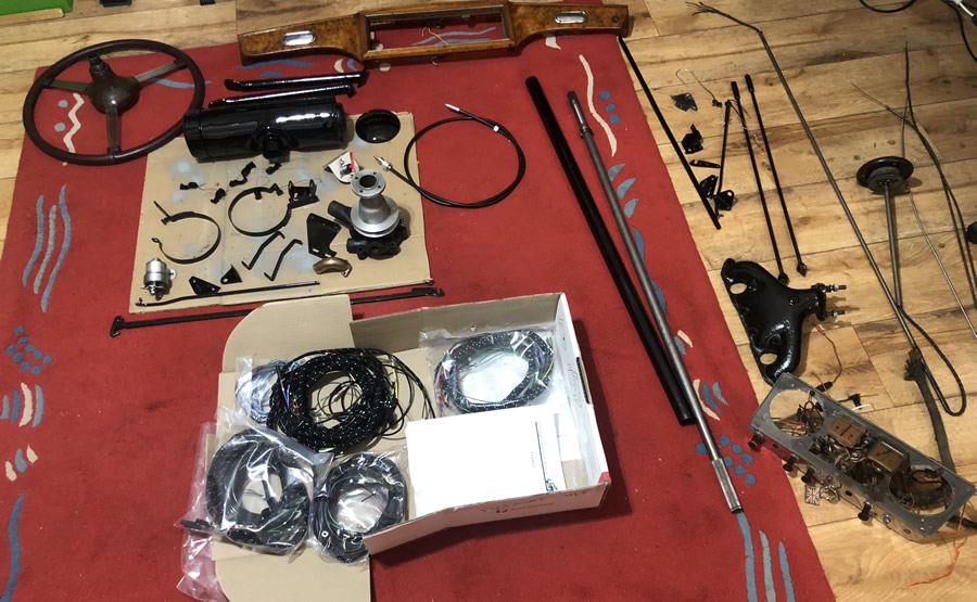
Stored "refreshed" parts are building up in the spare room.
 |
This is the new wiring harness purchased from Vintage Wiring Harness in Victoria. Looks good! 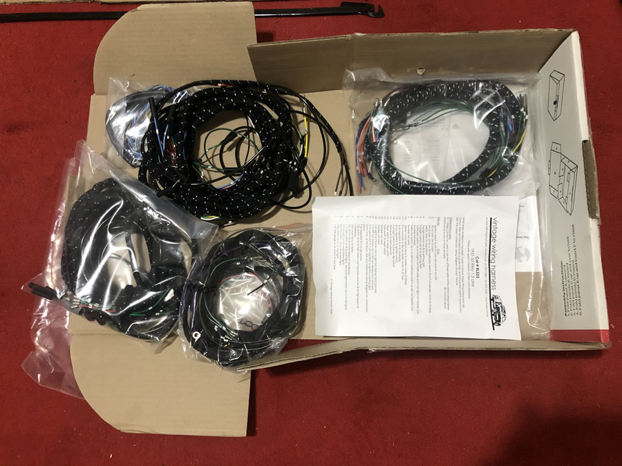 I have left the old wiring from the firewall to the tailights so that the new harness won't be damaged when it is pressure washed - soon. |
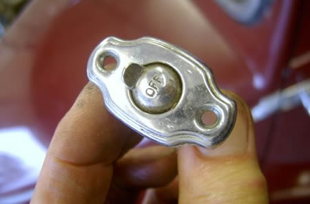
One of life's little mysteries? My Riley RME has 2 interior lights and the instruction book says "operated by means of individual switches attached to each unit" I give up - I can't find them or it! Where are they? 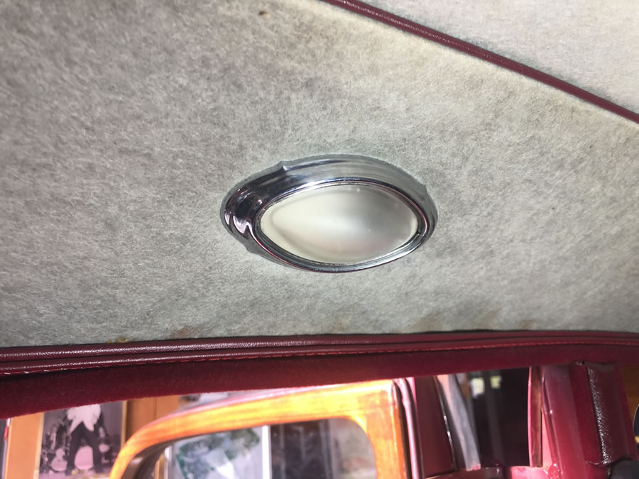 I'm pretty sure I have found the switch - under the replaced headlining - above the driver's door. The web or the UK Forum revealed the shape of the interior switch |
VIDEO: - This little video shows one of the Trafficators rebuilt and fuctioning. The electro- mechanical mechanism was in fair condition and was carefully cleaned. The arm was broken but I was able to insert some pins into the plastic arm and epoxy it back together. Page 3 shows more details and the LED Module.
|
By feeling along the headlining I was able to locate this switch by its distinctive shape. I will carefully open a small slit in the headlining, remove the switch and make a plate to fit behind the switch and over the lining(?) Next page revelas the location. |
I need to get the taillights working for rego and I decided to use LEDs. The wiring was a bit rough. 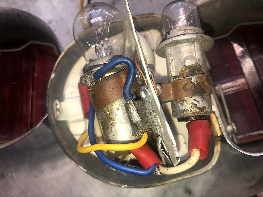 |
But the housing were OK so I stripped out the non-original bulb mountings to solder new ones in place as below. 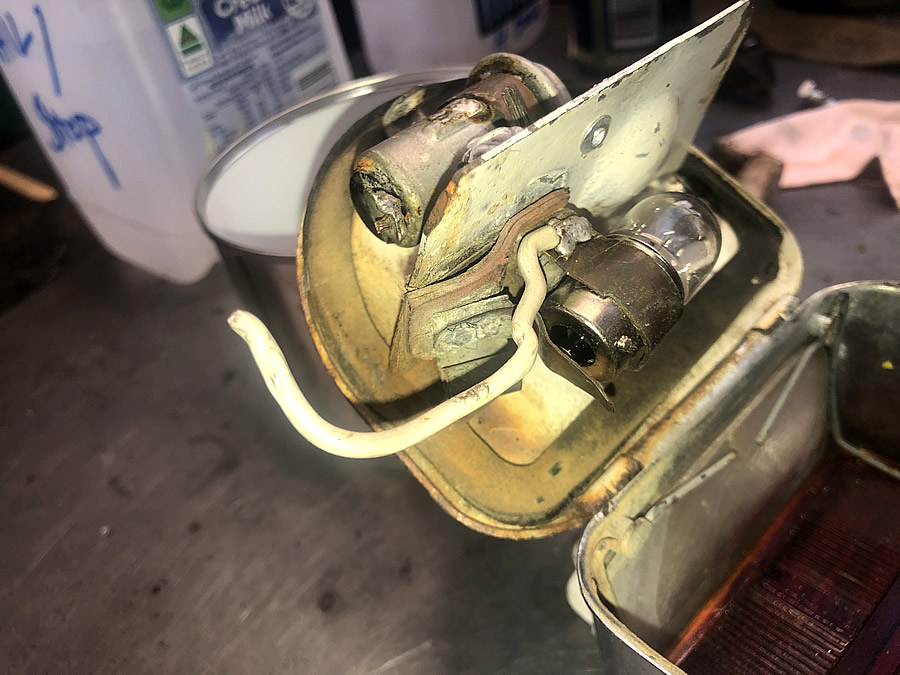 |
Quite a bit of debris! 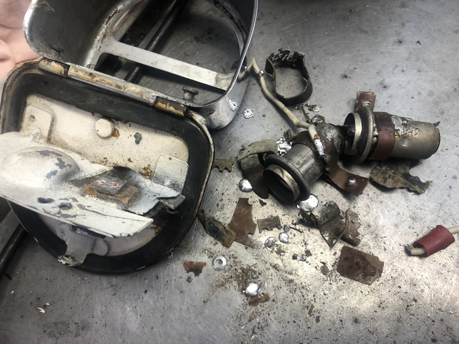 |
A trial fit of some LEDS for Tail (L) & Brake (R) 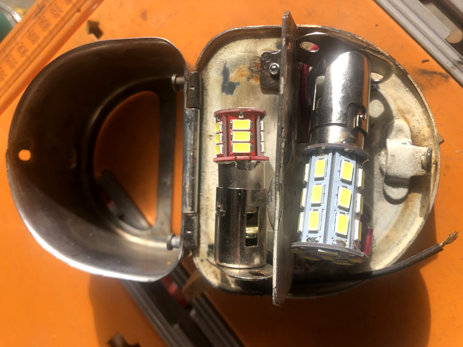 |
The head was trial fitted with thermostat housing, heater outlet and water pump but I was baffled by the bypass bronze casting. There is a small plate that has some sort of seal but I was advised that it usually leaks. The bypass has been blanked off at both ends. 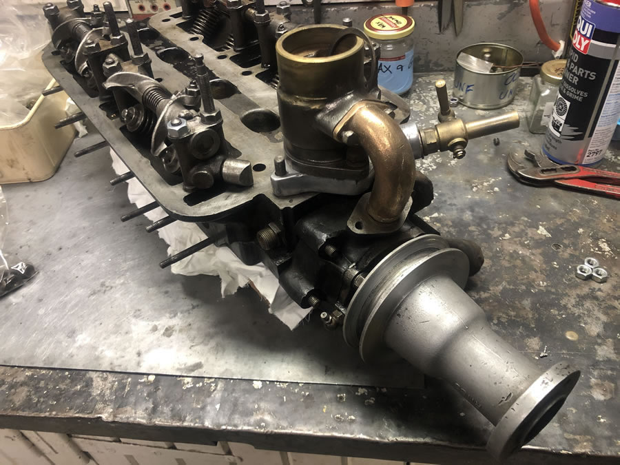 |
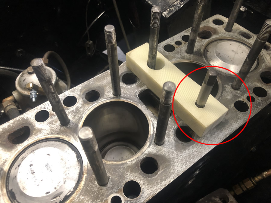
THIS was a bit of a setback. This is one of the head studs which obviously needed replacing as it's stripped in the block. The LH end clearly shows that it is very stretched. I only use the recommended 40 ft-lbs. torque. I fitted a heli-coil (3/8" BSF) in the head and replaced all studs and nuts. 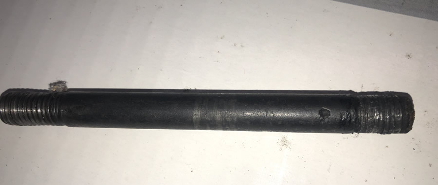 To make sure the drill and tap required in this fitting process are square to the block, I made a guide block from a very square & rigid piece of laminated fibreglass I had on hand. The opposite head stud will be used to clamp down the guide & here I have a 3/8" tap in the old hole to check whether the guide would work. |
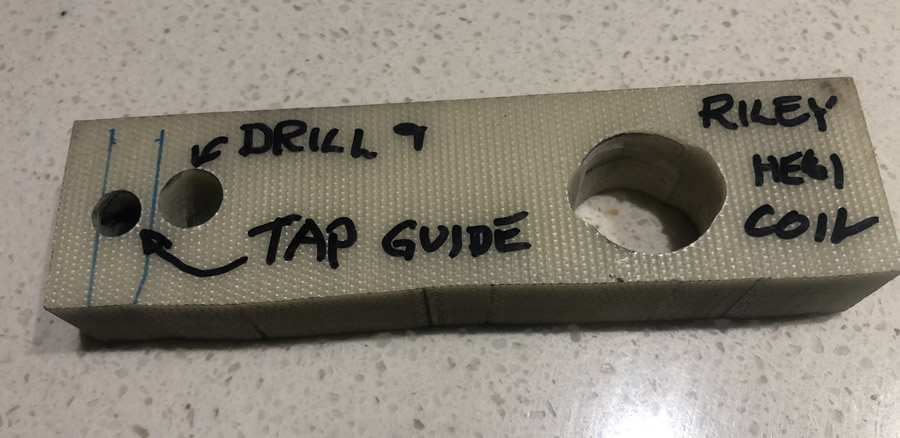
The block had a stripped thread and here the guide block (below) was first used to drill out the old thread then the 2nd guide hole was used to to steady the tap. 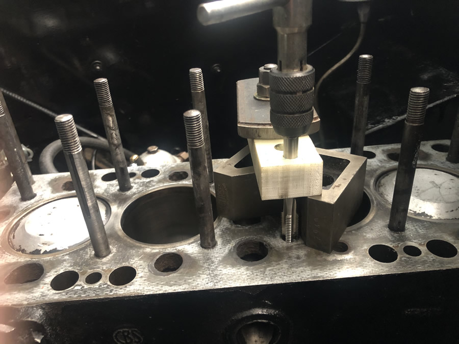 |
 |
 |
|
This tool comes with the kit to screw in the heli coil. 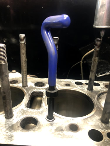 |
Time off to rebuild the single 1 1/4" SU 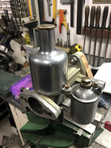 |
The thermostat housing and the body of the pump have had the bypass ports sealed with 5mm brass plates. 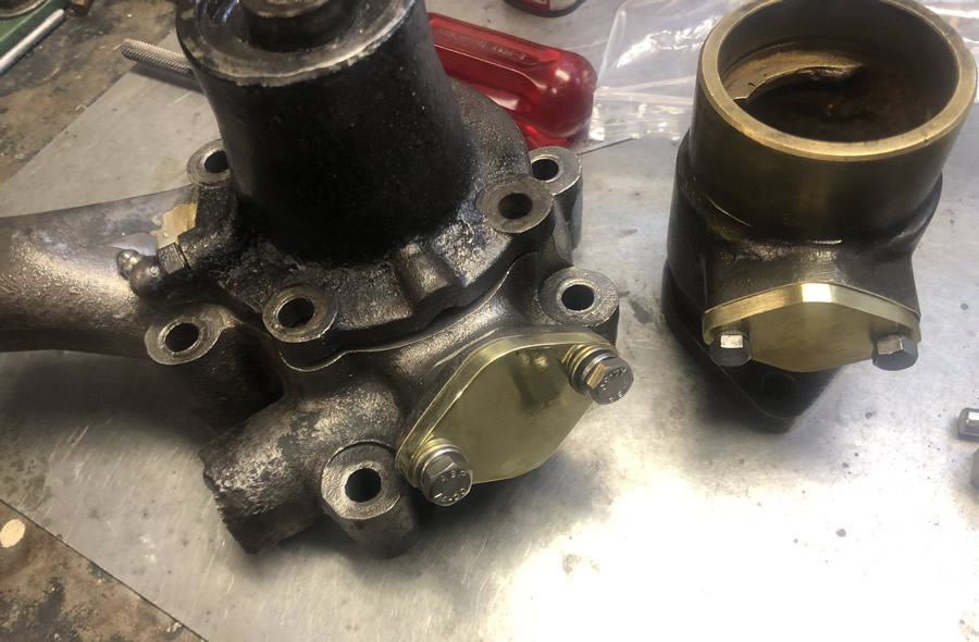 |
The water pump has been re-configured as I decided to fit a thermofan and electric water pump in lieu of the mechanical impeller. 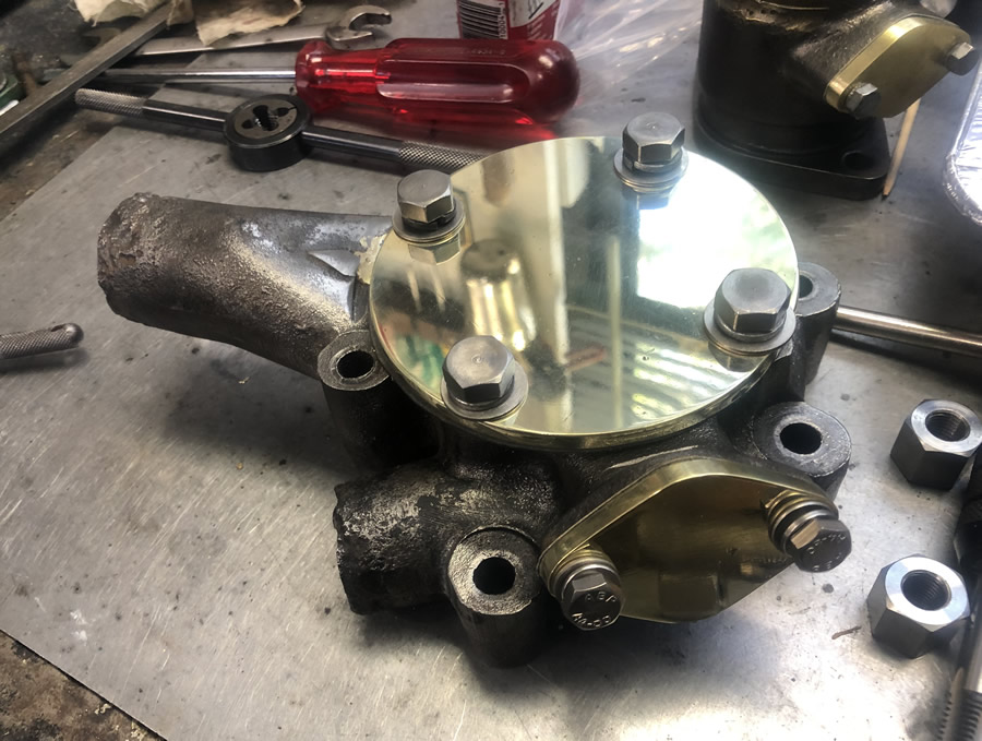 |
Finally - the head has gone back on the Riley. 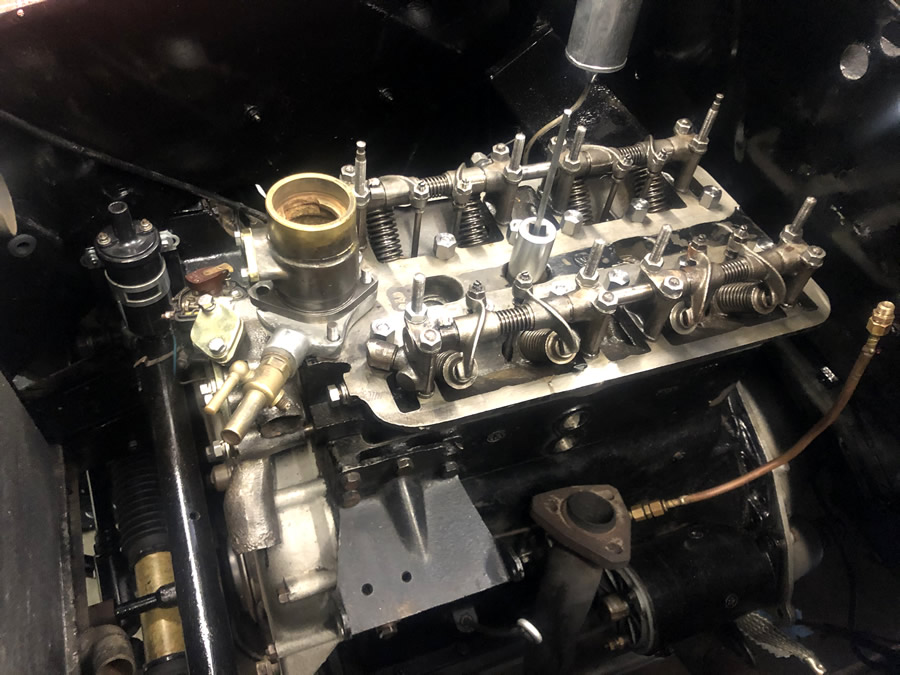 |
The rocker covers have been cleaned and polished; the SU is back on; the fuel pump cleaned; exhaust manifold & exhaust pipe reconnected and a trial fitting of the water inlet manifold 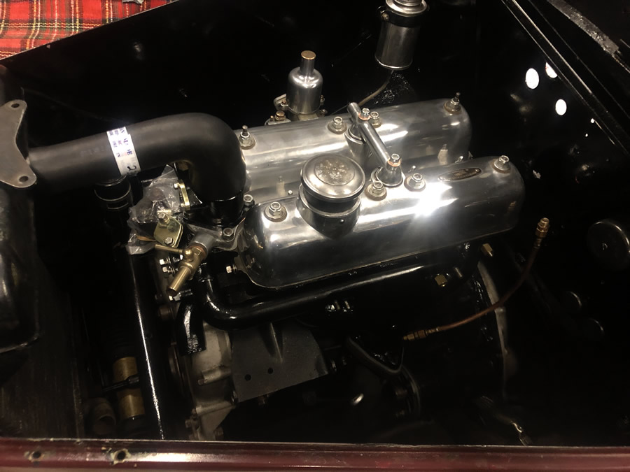 |
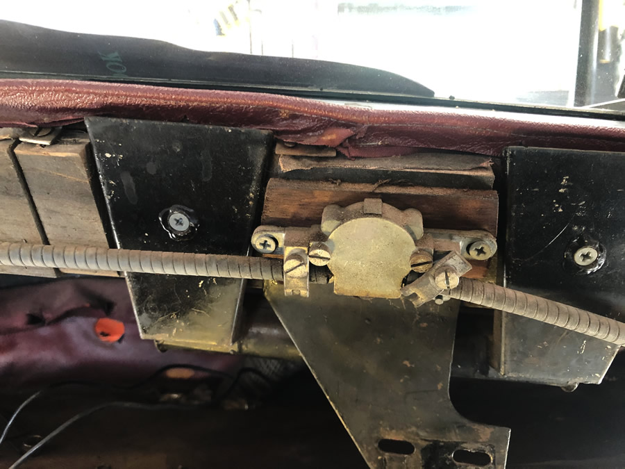
The solenoid has been installed and the battery to starter heavy current cables are in place between the battery / safety switch (next image) / solenoid / starter motor and engine-chassis ground (negative). 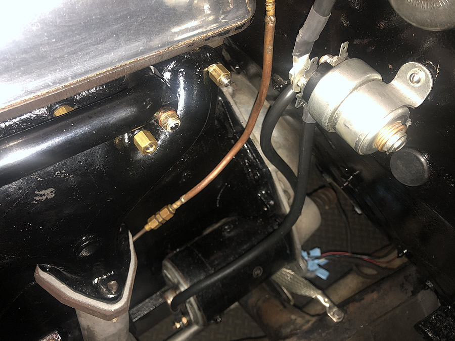 |
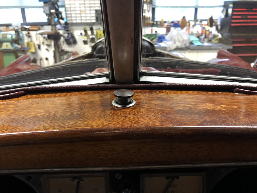
The parcel/ "glove" shelf had to be recovered before wiring could be installed. The first task was the safety switch which can be seen under the shelf. I can reach it from the driver's seat and it isolates the negative side of the battery from the engine-chassis ground (negative). . 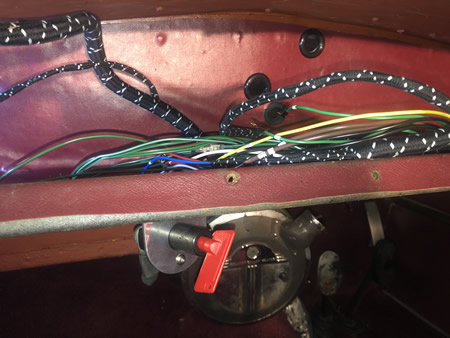 If the smoke starts to "get out" the switch is easily reached to cut off all power. It also provides limited security from casual theft. The new wiring loom is starting to go in when I get my head around the wiring diagram and the printed loom directions. |
VIDEO: - This little video was trial of the starter motor and solenoid, which was manually operated from the button on the near end. For normal starting the solenoid is activated electrically by the starter button. During this test I did a quick compression test and and was reasonably pleased. One little suggestion, don't leave your TDC tool screwed into the sparke plug hole - mine was launched into space but stopped by the shed roof and landed back neatly near where it started!! - shame I didn't get that in the video.
|
ELECTRONIC IGNITION 1. I checked out the distributor, cleaned everything and set the new points. Then I made the decision to fit an electronic module. I chose the Pertronix Ignitor Electronic Ignition Model LU-146LS for a 1953 Riley RME 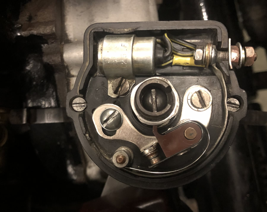 |
ELECTRONIC IGNITION 2.
I have been running electronic ignition systems for over 20 years and have been very impressed with the performance. They are an unobtrusive addition to a classic car fitted with a distributor. There will be little to suggest that there is such a sytem in the Riley. I never have to adjust points and have improved performance as a result of signifcantly higher kV at the plugs. 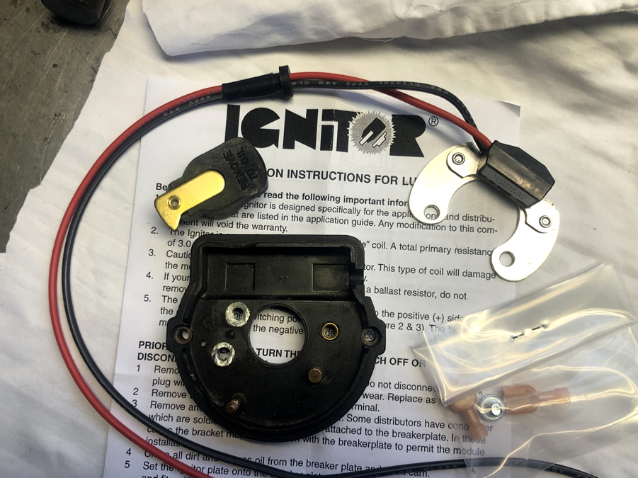 |
ELECTRONIC IGNITION 3. This was a test run of the module in place. There is not much to it. The module just responds to the each lobe on the cam going past and tells the coil to fire! No condenser is required. 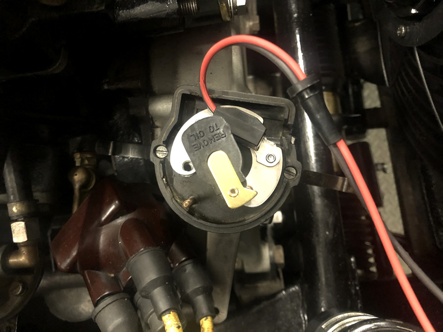 |
ELECTRONIC IGNITION 4. In my distributor the mounting screw point (indicated by the screwdriver) was a little above the moulding and stopped the ignition module from sitting flat. I had to machine it off a little with a dremel. 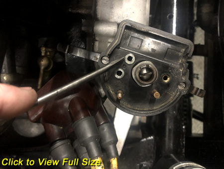 |
ELECTRONIC IGNITION 5. The module mounting plate did not quite match the hole used to screw the plate down. I carefully filed the hole in the mounting plate to match the tapped hole. 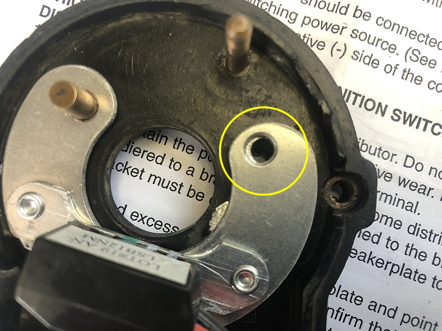 |
ELECTRONIC IGNITION 6. Now the plate fits. As the base is insulated, the plate needs to be connected to earth and I used the nearby screw to the left as it is tapped straight in to the distributor base. 2 solder tags wer used to make the connection but a piece of copper braid could be used. 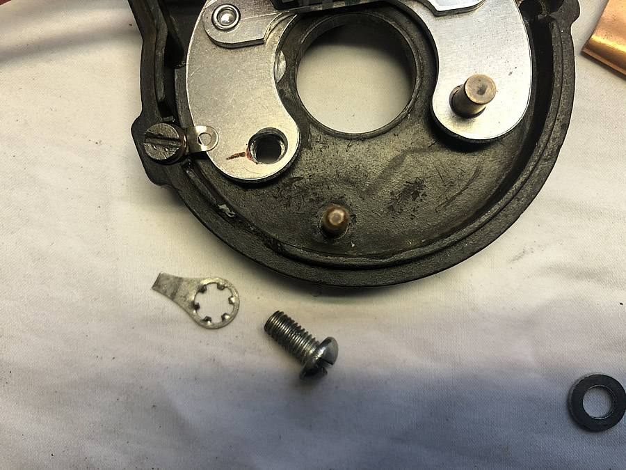 |
ELECTRONIC IGNITION 7. The solder tags are in place and ready to solder together. 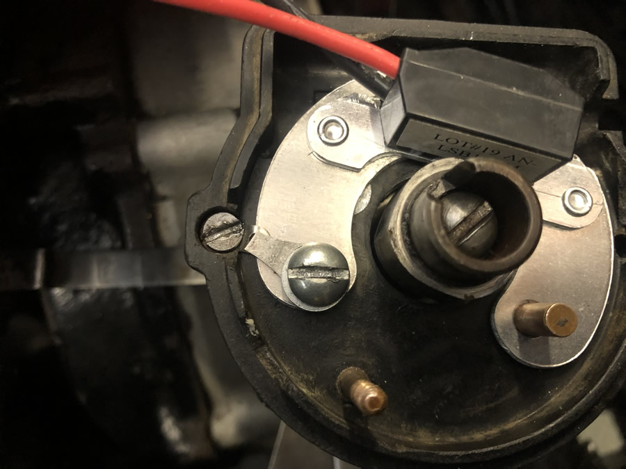 |
ELECTRONIC IGNITION 8. Soldering is done and the metal mounting plate is checked with a multimeter to see if it a perfect connection to earth (engine block). A normal coil is used for the Riley and should measure about 3 Ohms across the + & - terminals. The red wire goes to + on the coil and black to - 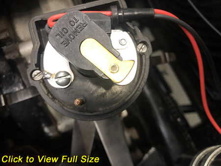 |
ELECTRONIC IGNITION 9. This is the type of distributor fitted to my RME 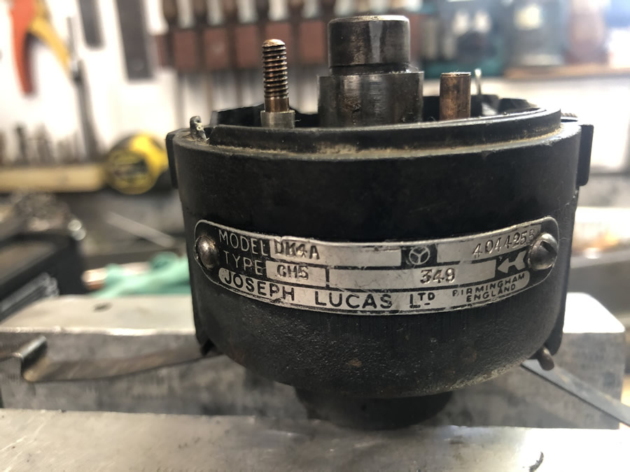 |