| Click the Pic to view Full Size |
|
|
|
|
|
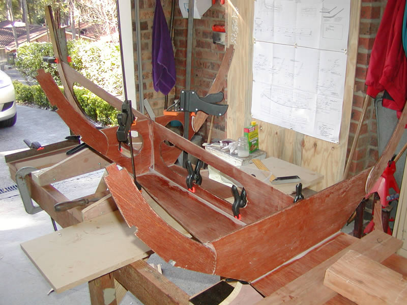
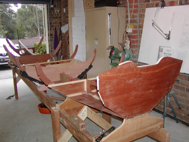
1. The stem & frames 1 & 2 are epoxied in place.
Date: 9th Aug 06 |
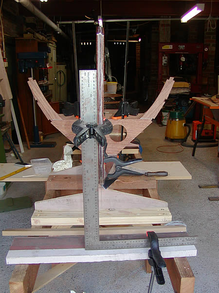
2. Great care was taken to see that the stem remained square to the level building jig. |
3. The fastening of the bottom plank to the jig was inadequate & was later replaced with self tappers. |
4. Reinforcement pieces for the transom have been "biscuit" joined with epoxy using the tracing as a positioning guide.. |
|
|
|
|
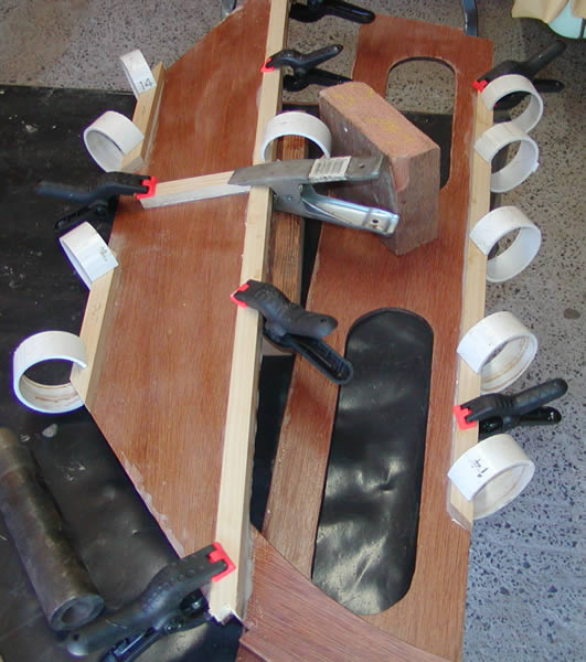
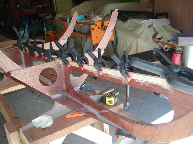
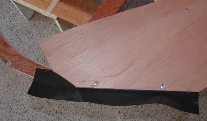
5. The transom profile is traced onto the reinforcement. |
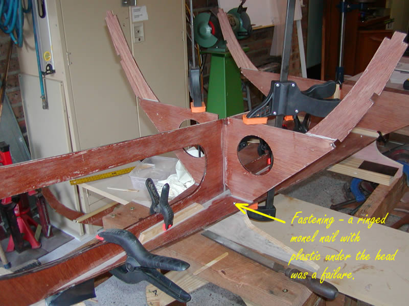
6/7. The internal shape is traced with transfer paper and the shape cut out with the jig saw. Note that I have raised the transom cut-out. I will be launching stern first from a wharf & need the extra freeboard. |
8. The cheap spring clamps are excellent for gluing and I have a bucket full of them. |
|
|
|
|
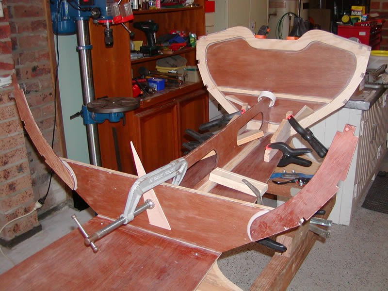
9. Some positioning jigs gave the correct transom angle ... |
10... and the whole stern section was test fitted. |
11. Supports were cut for the rear thwart and vertical spine ... |
12... and then epoxied using weights and clamps. The top edge of the seat support was bevelled. |
|
|
|
|
13. Frame supports added using clamps cut from PVC water pipe. |
14. One front seat support is fitted but the plan dimensions seem to be incorrect and the support is fitted to match the height of frame 1 and the stringer positions. |
15. The port side bow seat support is added - the dimension problem mentioned left a recess above the ply spine & I filled this with a strip of timber.
|
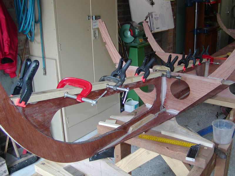
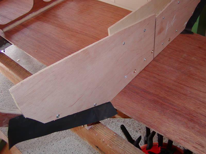
16. Frame 5 to the transom is epoxied in place. Pressure can be applied with the spring clamps by using short pieces of scrap timber. |
| |
|
|
|
|
|
|
|
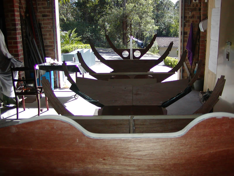
17. Last minute pressure often needs to be applied by means of anything at hand, in this case a spirit level propped to the bench! |
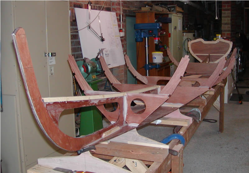
18. It's actually starting to look like a boat now. |
19. Frame 4 has a trial fitting. |
20. The edges of the temporary frame support were protected from epoxy with some plastic. |
|
|
|
|
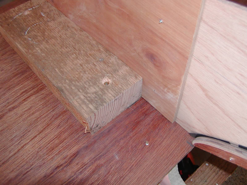
21. Frame 4 is supported in place by a scrap block slightly bevelled so that the frame is vertical. |
22. This shows the plastic epoxy shield in place.
|
23. Everything was continually checked for level and square. |
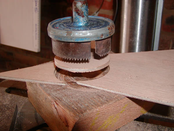
24. The hole saw was used to cut circles of ply from which the frame doublers were made.
Date: 17th Aug |